Introduction
One of the most incredible things about game design is the ability to do things that are impossible in reality. A chief example of this is the idea of the orthographic view.
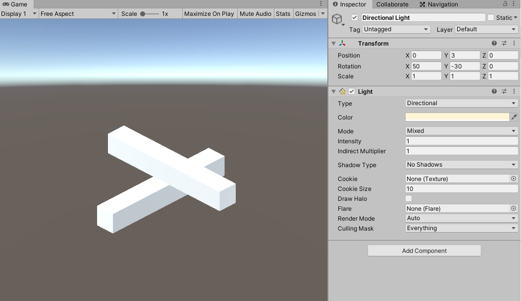
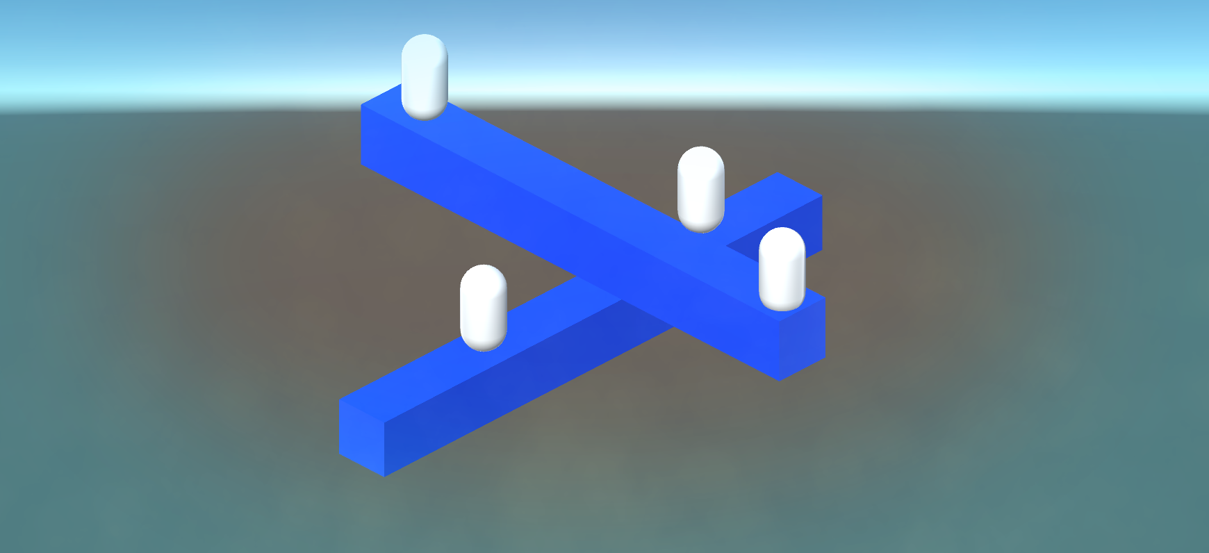
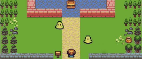
Computers have the ability to construct a perspective that does not even exist in real life. This has some fascinating consequences when it comes to creating video games. Exploring ways to utilize this unique perspective will generate a quite intriguing game. Not only will it be unique, but it also adds another dimension of design possibilities. This look is also quite similar to certain popular video games on the mobile app stores.
In this tutorial, we will learn how to use orthographic view to create a puzzle game in Unity. From generating an orthographic projection, to creating a character, we will explore all aspects of this novel perspective for game development. Simultaneously, we will also be learning about Unity’s Navigation component system and how we can manipulate that to work in this multi-faceted view.
So, without further ado, let’s get started and create an illusion game!
Want to jump ahead? Check out Part 2 instead!
Assets and Project files
You can download the completed project files for this tutorial here: source code.
We will also be using the Navigation Component system which can be obtained for free from Unity’s Github (https://github.com/Unity-Technologies/NavMeshComponents). Download it to your computer and save it in a file near your Unity projects. We are going to be accessing this later.
Creating the Illusion
Select your camera and change the perspective to “Orthographic.”
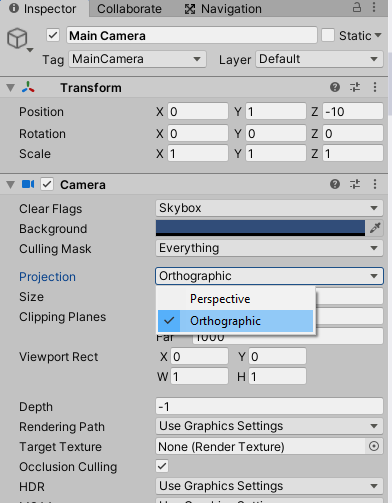
The way this view works is it takes all depth information and flattens it. This way, the size of objects in the scene is their “true size,” meaning that far away objects do not look smaller and closer objects do not look larger. This, you can imagine, is essential when it comes to creating this illusion.
We can create this illusion using only cubes, so go ahead and add one in.
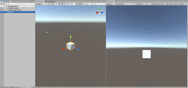
Our camera isn’t in the right position; we need to fix that. The position isn’t as important as the rotation. We want it to be rotated around the X and Y axis so that we can essentially see three faces of the cube at the same time. Here are the final position and rotation I landed at:
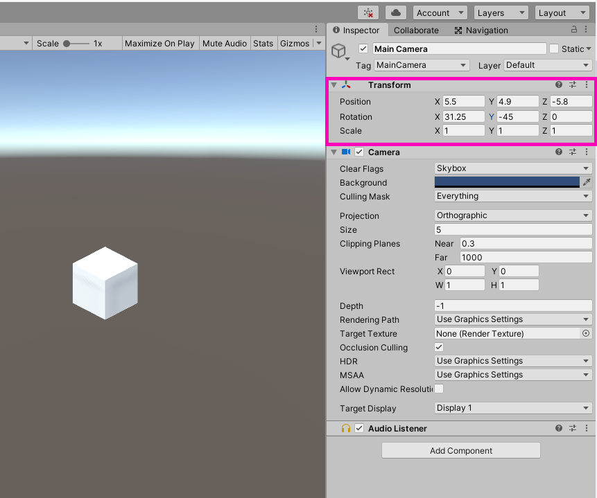
It is super important to never change the transform of the camera! Once you have a value, lock it in, do not change it. Do not write scripts moving the camera. Do not make animations moving the camera. In order for the illusion to work, we need the camera to always stay in one single position.
Once the camera is set up, we need to create an illusion we can work with. Scale the cube so that it is fairly long on one axis
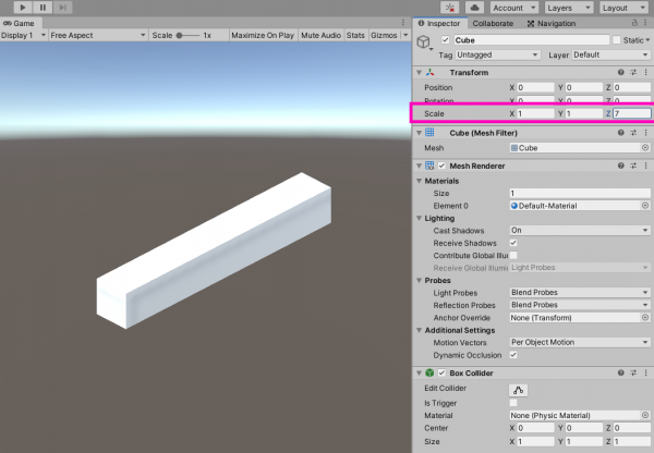
Next, you’re going to want to duplicate the cube and rotate the duplicate 90 degrees on the Y-axis. Position it so that it looks like this:
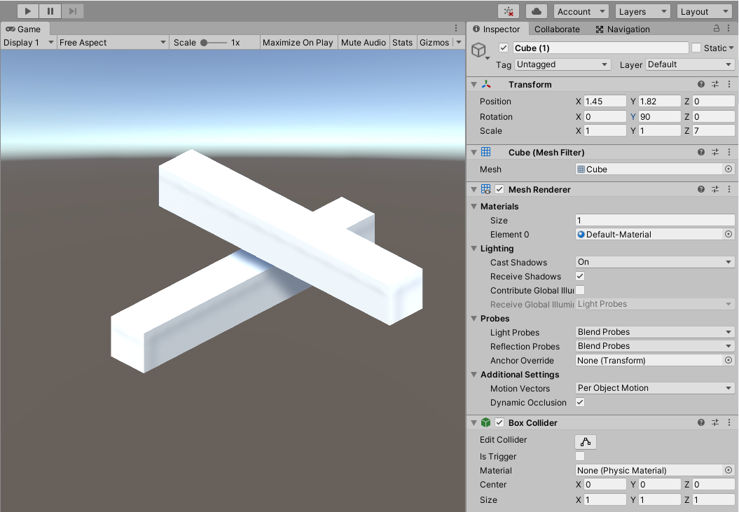
Bring it up above the original cube a good distance for reasons we will see later.
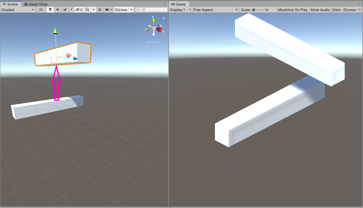
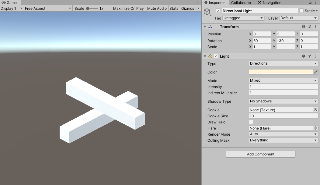
Reposition everything so that the final result looks like this:
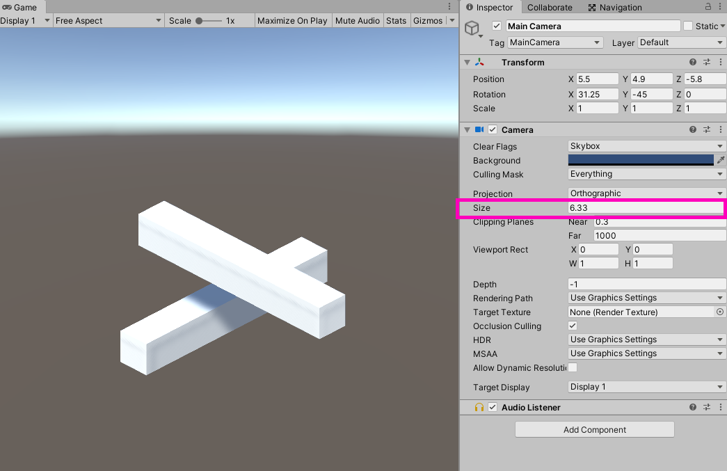
You may have to either change the position of both cubes or change the “Size” on our orthographic camera. Also, disable shadows on the directional light. This is another important part of creating the illusion.
Cleaning Up The Environment
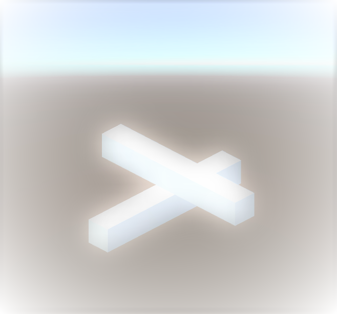
I have a couple of complaints with our current setup. First, everything is so bright!
Let’s add in some materials. Create a new folder called “Materials” and create a new material called “Blue.” Change the Albedo value to blue and drag this material onto both of our cubes.
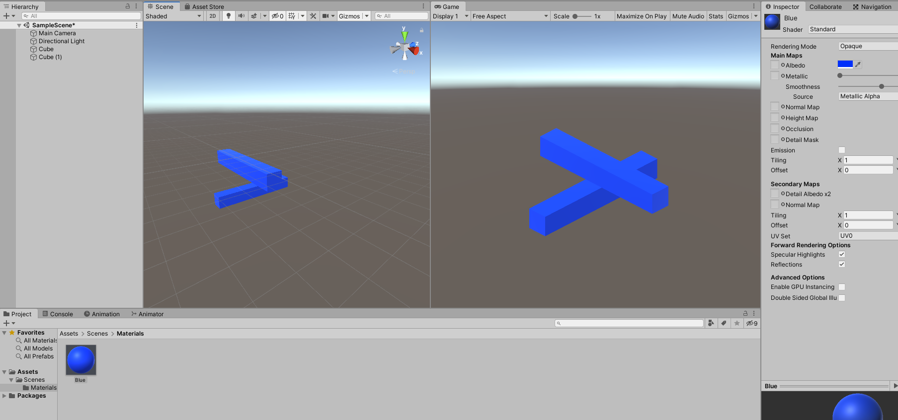
That looks much better! The second thing we need to change is our hierarchy.
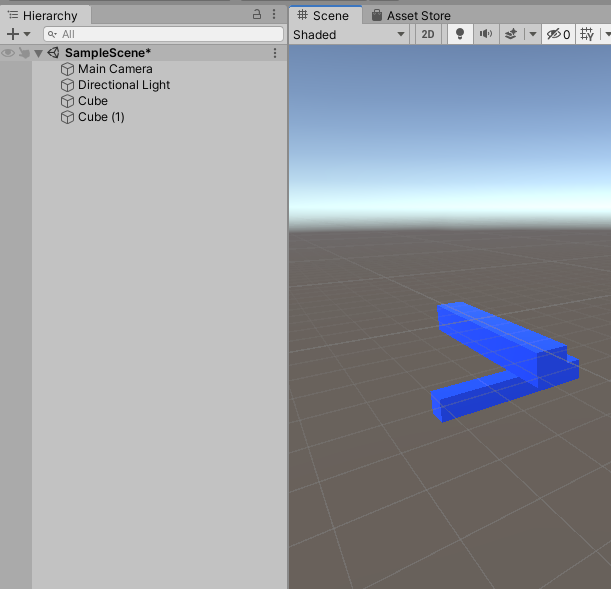
It looks so un-organized. Plus, the scale of our cubes will present problems later on if we try and animate them. So first, let’s create an empty game object called “Environment” and place our cubes in that.
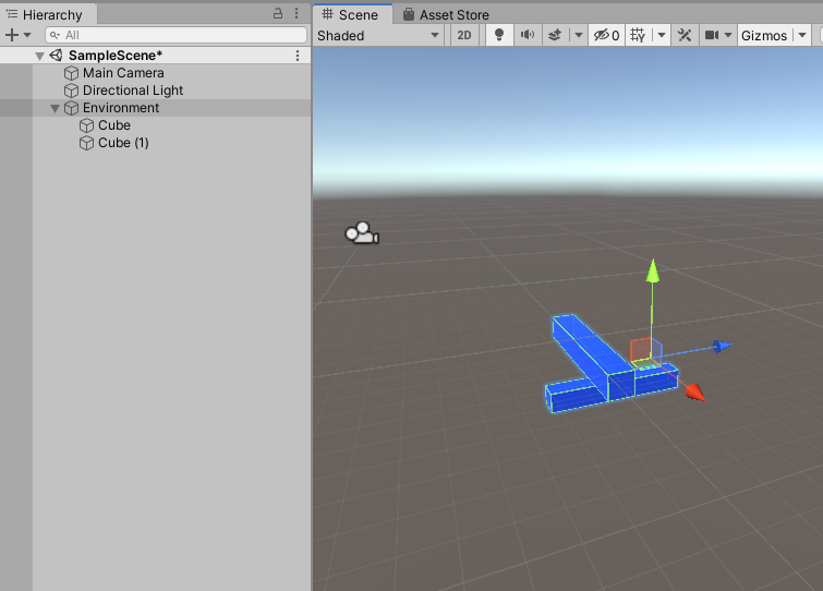
Next, let’s further parent our cubes into empty game objects called “PlatformTop” and “PlatformOccluded” so that they’ll each have a uniform scale of 1.
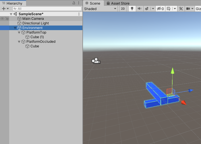
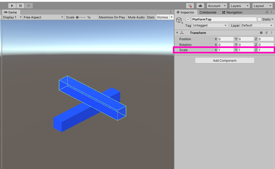
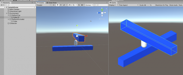
There we are! A nicely setup scene that we can work with. As a very final step, create a capsule called “Character” and place it on our cubes.
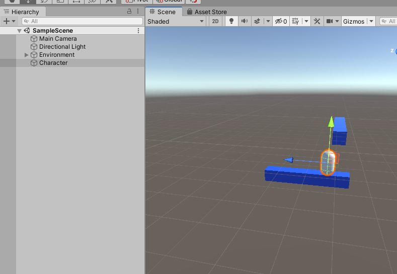
Since this is going to be our character, you might consider changing the size of the environment (change the scale of the children, not the parents which must stay at 1). The character should easily fit under both of these cubes
Setting Up Navigation
Agents and Nav-Meshes
In your project files, create a new folder called “Navigation Components.” Navigate to where you stored your downloaded Navigation Components from Github and drop the “NavMeshComponents” folder into your project tab (this is located in “NavMeshComponents-master -> Assets”). There are some examples in the entire folder that are worth checking out in a separate, dedicated Unity project. When the folder is done importing, you’ll notice the presence of a few more scripts in the “Navigation” category of the components.
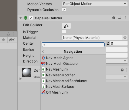
If you’d like a more in-depth look at what exactly these components do, check out the tutorial on the Game Dev Academy about Unity’s native navigation tools (https://gamedevacademy.org/learn-unitys-navmesh-by-creating-a-click-to-move-game/). For now, assign a “Nav Mesh Agent” to our character capsule.
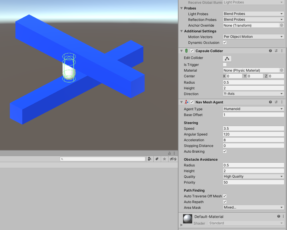
A “Nav Mesh Agent” is a game object which traverses a nav mesh. Basically, this is the game object that’s going to be doing the path-finding. Most of the settings in the agent component are fairly intuitive. I suggest, in order to better understand what each of these settings do, fiddle with these values when we’ve got the character on a working nav mesh. What I mainly want to highlight here is the cylinder shape surrounding the capsule.
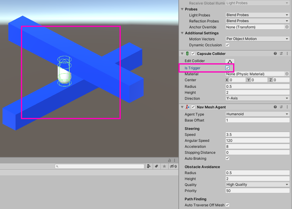
In addition to the capsule collider (which should be set to “trigger” by the way), we’ve got an extra boundary being created. The size and radius of this cylinder is the size and radius that Unity will think the navigation agent is. This isn’t a value we can’t edit this value on the Nav Mesh Agent, rather, when we get to it, we will actually be editing this on the nav-mesh itself.
But what is a Nav Mesh exactly? A nav-mesh is an actual mesh generated by Unity which allows the agent to make paths on its geometry. Any place where there is a nav-mesh is a place where the nav-mesh agent can generate a path. Having said that, we’re going to want a nav-mesh on both our cubes. Select the parent of each cube and add a “Nav Mesh Surface” component to each.
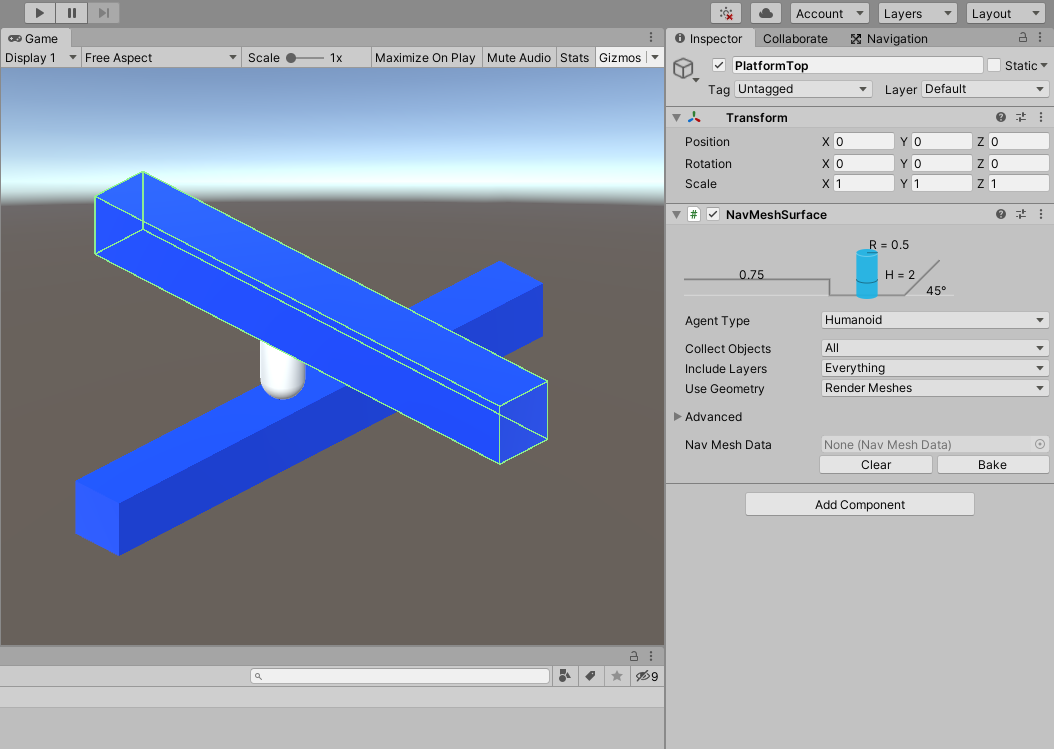
The settings for this component are worth looking at. First, you’ll notice that there is an “Agent Type” field. This is set to “Humanoid” by default. The idea behind this value is that you could set different types of nav-mesh agents (things like animals, enemies, etc.) if you wanted them to path-find differently. Since “Humanoid” is what our character is, we’re going to leave this at the default value.
“Collect Objects” determines which surfaces are going to have a nav-mesh baked onto them. In our case, we want this set to “children” since that is where are cubes are. “Includes Layers” allows you to determine what render layers you want to be involved in the nav-mesh calculation. And “Use Geometry” allows you to set whether you want the geometry or the physics colliders belonging to the game object to be considered viable nav-mesh surfaces. Finally, there is a “Bake” and “Clear” button at the end of the component. Hit “Bake” for each of the components we created. Unity will then generate the nav-meshes and your viewport will look like this:
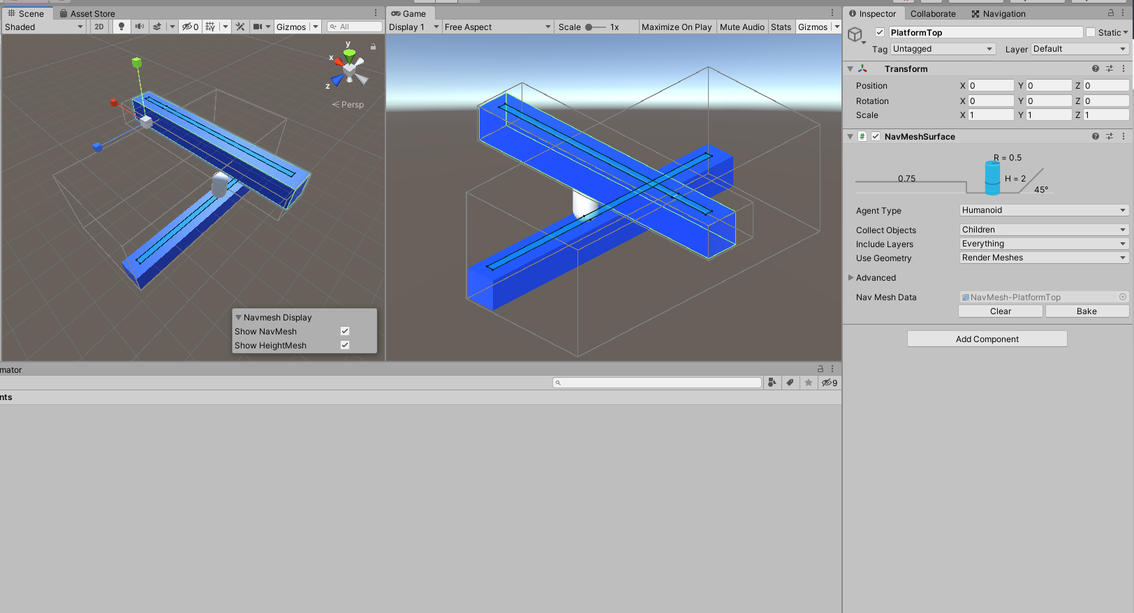
That little blue sliver is our nav-mesh. Let’s test to see if it’s working! Create a new folder called “Scripts” and create a new script called “PlayerController.”

In that script, we’re going to write out a simple bit of code that sends out a ray-cast, checks to see if it’s on a nav-mesh, and sets the clicked position to be the destination of the agent if the click was indeed on a nav-mesh.
using System.Collections;
using System.Collections.Generic;
using UnityEngine.AI;
using UnityEngine;

[RequireComponent(typeof(NavMeshAgent))]
public class PlayerController : MonoBehaviour
{
    private NavMeshAgent agent;
    private RaycastHit clickInfo = new RaycastHit();

    // Start is called before the first frame update
    void Start()
    {
        agent = GetComponent<NavMeshAgent>();
    }

    // Update is called once per frame
    void Update()
    {
        if (Input.GetMouseButtonDown(0))
        {
            var ray = Camera.main.ScreenPointToRay(Input.mousePosition);
            if (Physics.Raycast(ray.origin, ray.direction, out clickInfo))
                agent.destination = clickInfo.point;
        }
    }
}
Drag and drop this script on to our capsule character. Hit play and watch the magic!
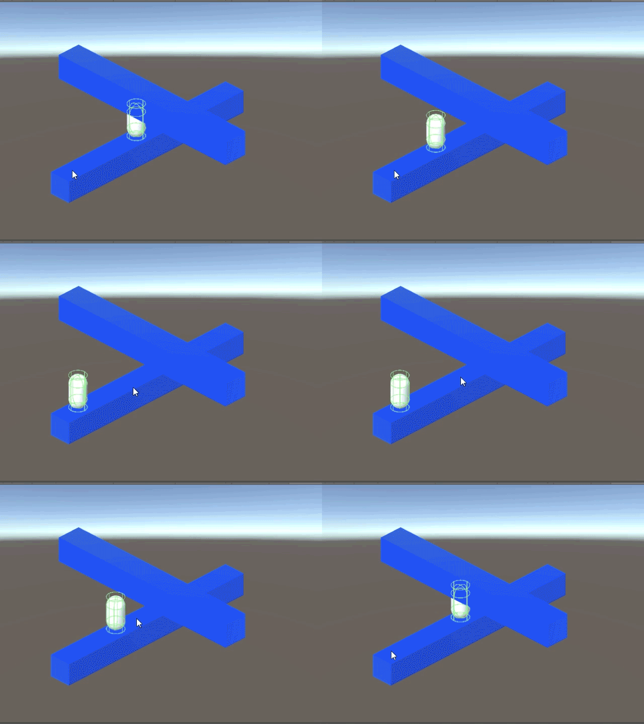
Our character now moves where we click! Note this, because we have the nav-mesh as a component, it exists on that game object meaning we can move the game object and our nav-mesh follows. This will be handy when it comes to animating the platforms.
Off Mesh Links
The entire purpose of this illusion was to make it so that surfaces that seem connected can be navigated by the player. As such, we want these two surfaces to be connected somehow.
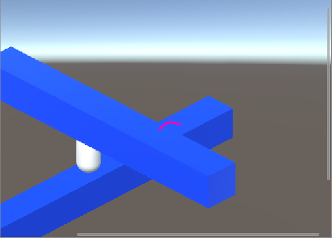
This is where Off-Mesh Links come in. Just like their name implies, they are a way to link two nav-mesh surfaces. Create a new empty game object called “Link1” and place it in the Environment.
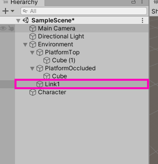
Add a “NavMeshLink” component (not an “Off-Mesh Link”) to this game object.
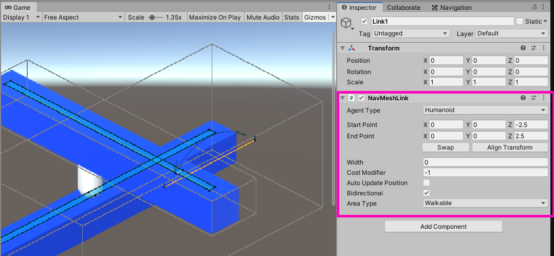
As you can see, we get two transforms. These are, intuitively, the start and end positions of our link. We need to place each transform on the occluded cube and another on the top cube. You will see a circle form when the transform is over a viable nav-mesh surface.
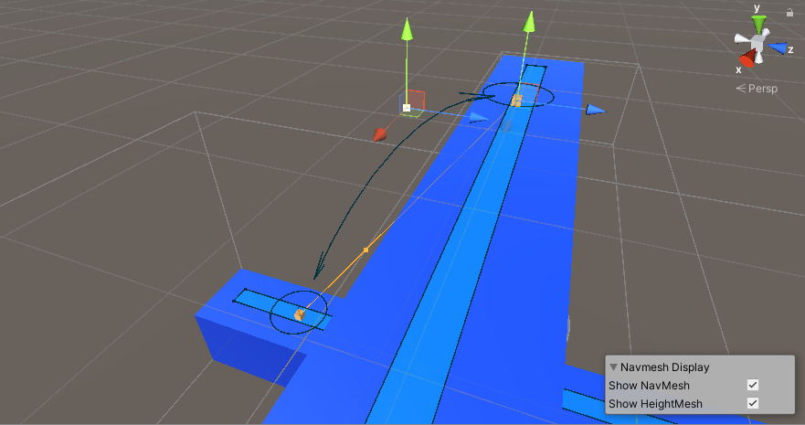
Now here is where the uniqueness of the illusion comes in. We need to strategically place these off-mesh links in such a way so that they align in the game view. This causes a disconnect in world space but an apparent connection in orthographic space.
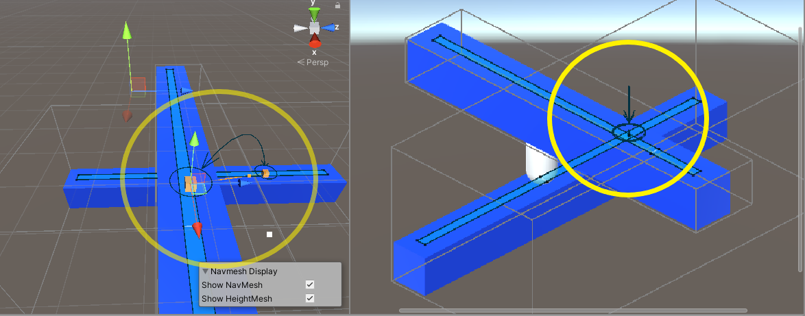
If you don’t see any of this in the game view, enable “Gizmos” in the top right corner. Our player now has the ability to navigate both cubes!
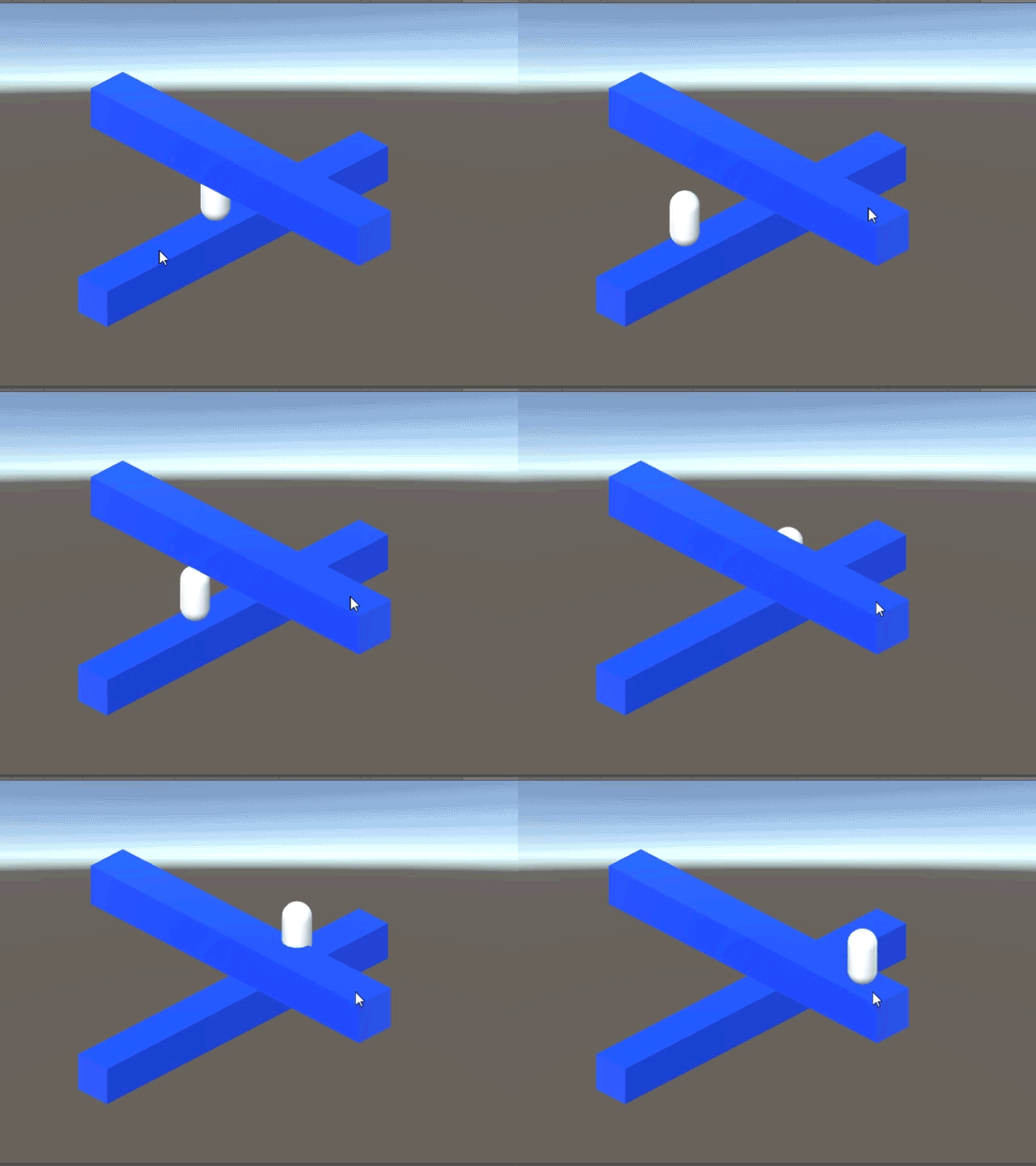
Cleaning things up
Right now, the mechanic works. Our player can navigate two disconnected surfaces. However, it looks all wrong. There is too much of a translational delay. We need it to be as seamless as possible. Now, we realize that it won’t look 100% seamless simply because we’re using a navigation system that wasn’t really built for what we’re using it for. This link system was designed for things like ladders or teleportations, not necessarily illusion upholding linkage. Nevertheless, we can make an exponential improvement to this atrocious way of crossing platforms. As soon as the player is on a link, we don’t want it to interpolate between the positions (causing a delay). Instead, we can make it instantaneously teleport through the link. To do this, we’re actually going to write a bit of code with our own method of crossing links. In the “PlayerController” script, we need to add this if-statement to our update function,
void Update()
    {
        if (Input.GetMouseButtonDown(0))
        {
            var ray = Camera.main.ScreenPointToRay(Input.mousePosition);
            if (Physics.Raycast(ray.origin, ray.direction, out clickInfo))
                agent.destination = clickInfo.point;
        }

        if (agent.isOnOffMeshLink) //New logic statement
        {
            agent.CompleteOffMeshLink();
        }


    }
“CompleteOffMeshLink” is a method we call on the navigation agent. It will instantaneously move the character through the off-mesh link whenever it is called. In our case, we’re calling this method whenever we’re on an off-mesh link.
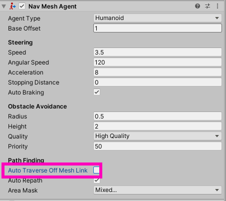
To test it out, make sure that “Auto Traverse Off Mesh Link” is disabled.
Hit play and let’s have a look!
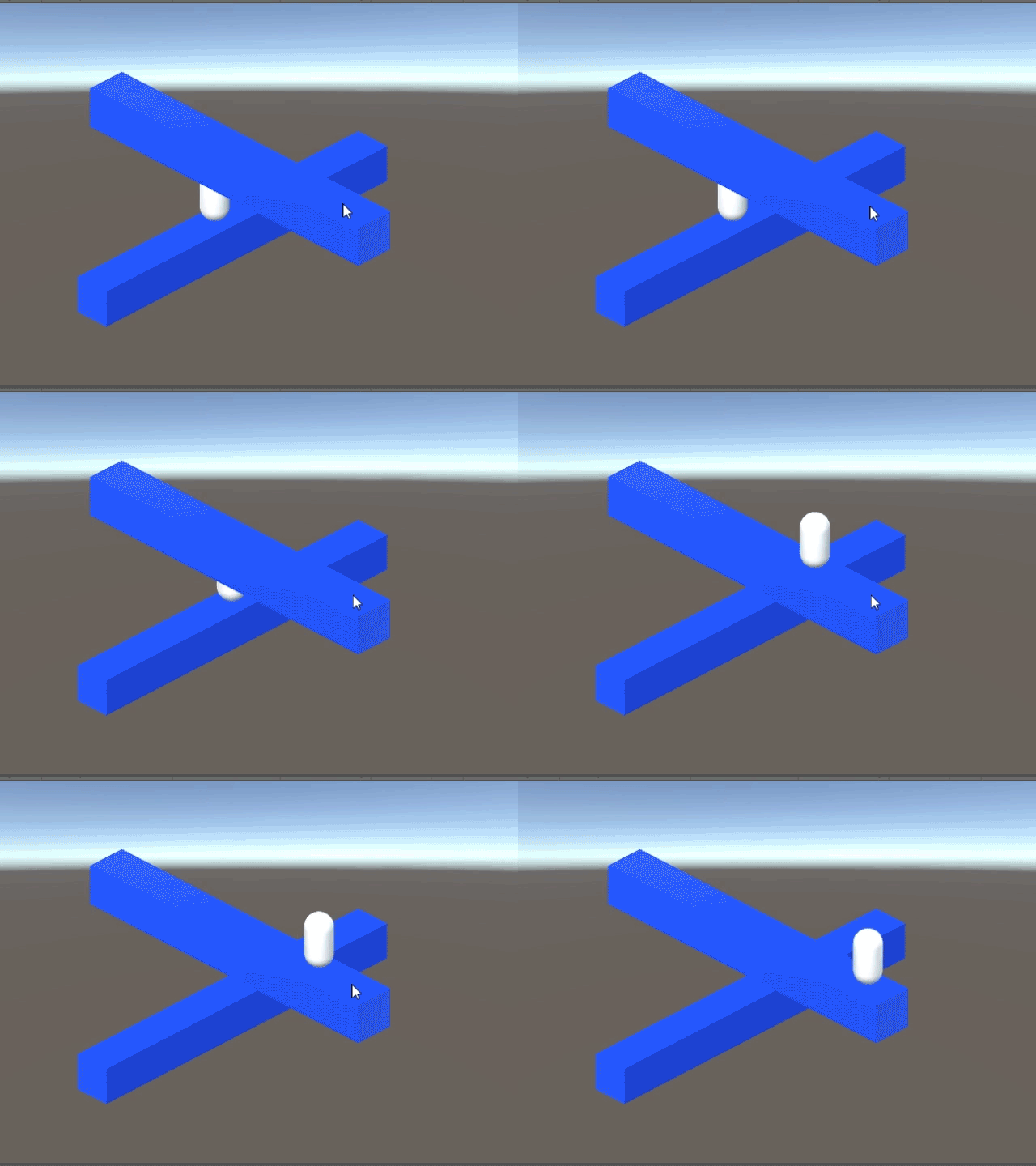
This actually is only a slight improvement. It’s much too sudden. It looks weird because the character just appears right in the middle of the platform. This is because our navigation mesh is right in the center of our platform.
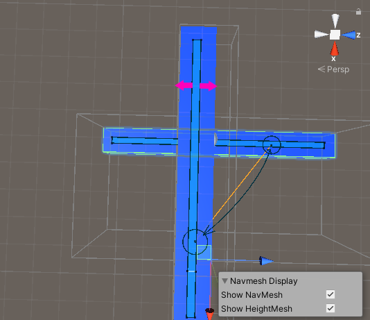
We can fix this by changing the agent size of the nav-mesh agent. Go to the Navigation tab and change the radius of the character to be a very small value.
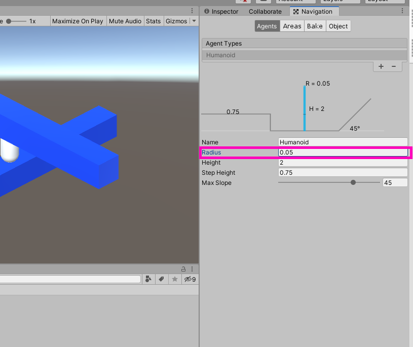
Go over our nav-mesh surfaces and rebake each of them. This will make the navigation surface cover the top of most of the cubes.
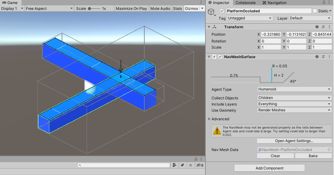
Notice, however, we have an error message.
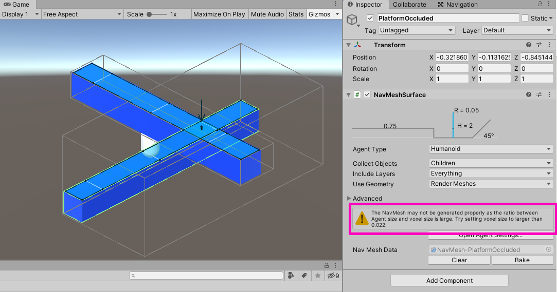
Basically, it’s saying that the navigation surface may not be accurate for such a small agent radius. To fix this, open “Advanced Settings,” check “Override Voxel Size.” Set it to the recommended size of 0.022. We need to do this on each surface component and then bake it as well. The error will be cleared when each surface has finished baking.
We need this navigation surface to cover as much of the platform as possible. To increase the precision of our linkage system, we can scale the top cube ever so slightly to be underneath all of the navigation surface.
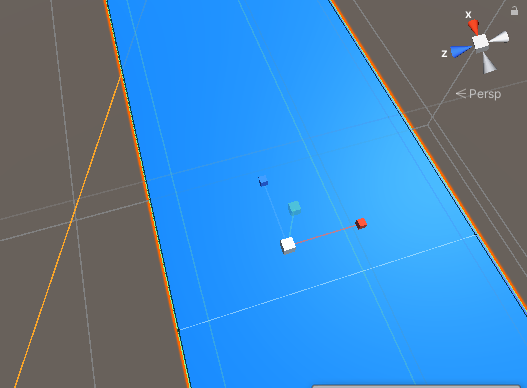
And now, it’s just a matter of strategically placing the links so that one of them is on the edge of the top cube.
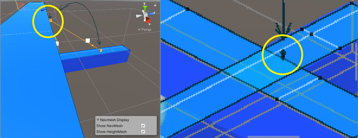
Now, hit play and test it!
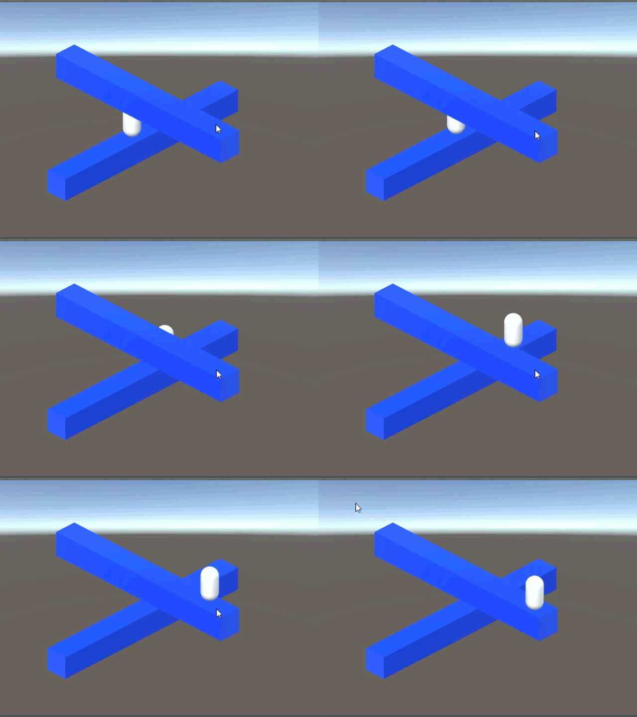
As you can see, this isn’t 100% seamless but it is an improvement to the previous look. To improve the “seamlessness” of the link, try repositioning the start and end points. It’s just a matter of fiddling with values. Even though it doesn’t completely uphold the illusion, it will certainly suffice for prototyping and level testing.
Conclusion
Whew! We’ve covered a lot of ground here and learned quite a bit about using Unity’s Navigation component system and orthographic views to create a game. Not only did we get our systems set up for our illusion game, but we also got our character moving!
However, while, we’ve got the ability to navigate disconnected platforms, it isn’t as seamless we can get.
In the next tutorial, we’re going to write a custom algorithm for interpolating between points. We’re also going to be animating platforms and giving the player the ability to trigger these animations from in-scene actuators. This might all sound a bit complicated, but worry not as we will walk you through each step to get it done!
Let’s continue this exploration of perspective as we…
Keep making great games!
