Check out the second part of this series!
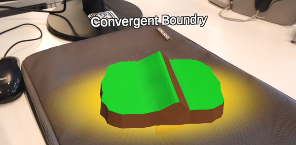
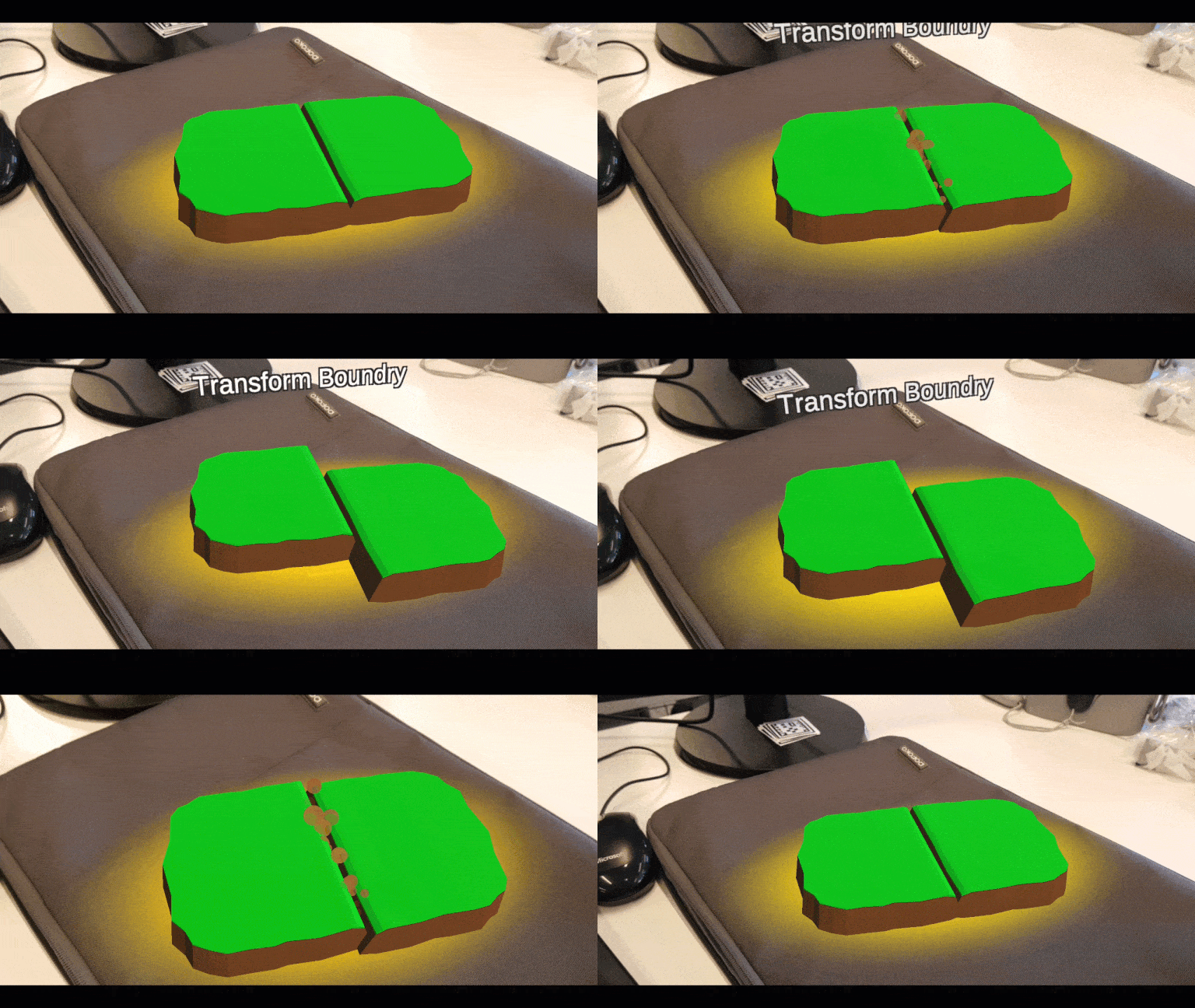
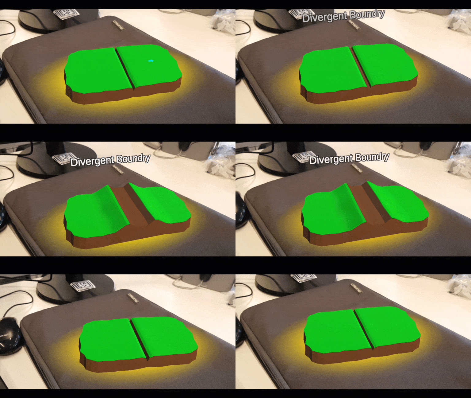
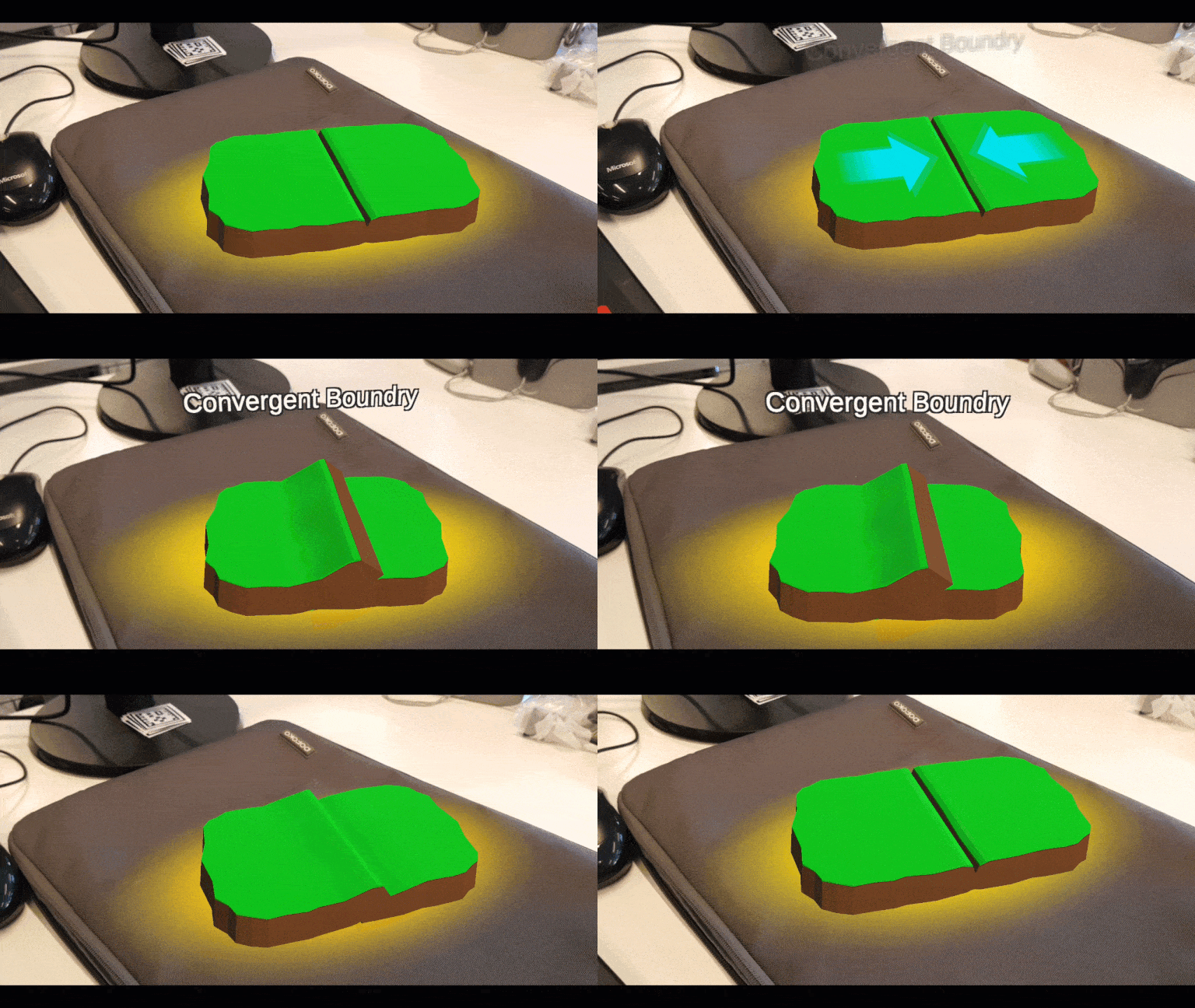
In this tutorial, we will be creating an educational tool to show off the different types of tectonic plate movement in augmented reality (AR). Here’s a look at the 3 different types of plate movement we’ll be creating. Each with their own specific directions you need to drag, in order for the animation to play.
Transform Boundary
Divergent Boundary
Convergent Boundary
How are we going to be rendering the plates at a certain position? By using an image target. An image target is way to project models in AR. These are specific images that the app can identify through your camera. It calculates the position and angle of the image and then projects a model or whatever you want on top of it.
The best types of targets are ones with lots of “points” that the app can identify and lock on to. This involves creating high contrast targets, with many edges and patterns that stand out. A good type of target, for example, would be a QR code, which is similar to the ones we’ll be using in this tutorial.
Project Files
This project has pre-made animations, timelines and models that are going to be used in this tutorial. You can download the project files here. The EasyAR SDK isn’t installed though. You can learn how to do that here.
Creating the Scene
First, we need to create a new 3D Unity project. Once that’s all set up, delete the “Main Camera” as EasyAR will take care of that. You should just have the directional light remaining.
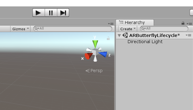
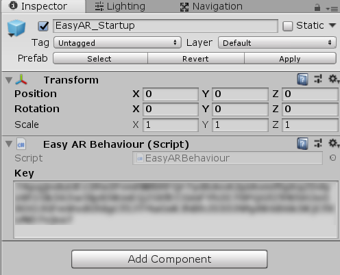
Now you need to drag the “EasyAR_Startup” prefab (EasyAR > Prefabs) into the scene. Once that’s done, click on it and enter in your SDK licence key from EasyAR into the “key” field.
Creating the Image Target
Now we’re going to create our image target. We only need 1, as both plates interact with each other by animations. This image target is only there for a real world positional reference.
Drag the “ImageTarget” prefab (EasyAR > Prefabs > Primitives) into the scene. Click on it as we need to change a few properties.
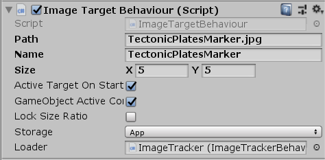
Set “Path” to “TectonicPlateMarker.jpg”. We have our image targets stored in the “StreamingAssets” folder and “Path” is the path to that image from the folder. Since we don’t have the images in any sub-folders, we can just directly link it. For “Name”, we just write down the image name (without file extension). Set “Size” to 5 for X and Y. This can really be any number, as it’s just used as a reference for us to resize the models to how they will appear in the app. Lastly, change “Storage” from App to Assets.
Now we need to link the image tracker into the “Loader” property. This is found as a child of the “EasyAR_Startup” object in the scene.
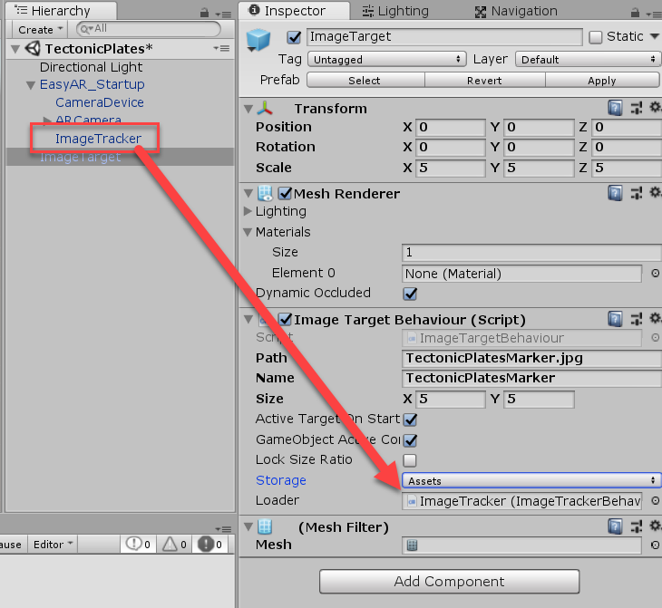
Finally, I renamed the image target to “ImageTarget_TectonicPlates”.
Importing the Plates
What we’re going to do now, is import the plate models, position them and get ready to animate. So first, create a new empty GameObject (right click Hierarchy > Create Empty) and call that “TectonicPlates”.
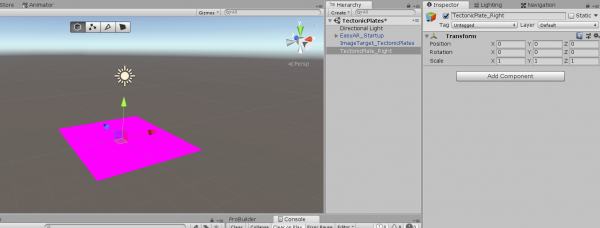
Then, drag in the “TectonicPlate” model from the “Models” folder into the scene, as child of the empty object.
Rotate and position the model like in the image below. The parent object should be at the center edge of the plate, where it will connect to the other one. I also scaled it a bit along the X axis to make it wider.
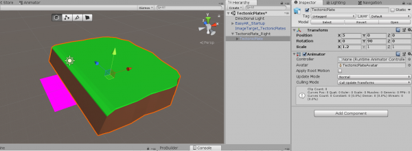
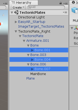
We’re going to be animating soon, but before we do that, let’s make it a bit easier. Right now, we need to modify 3 separate bones to make the model tilt upwards at the end. Let’s open up the armature child and create a new empty GameObject called “MainBone”. Set the Y position of that to be 0.015 and X and Z to be 0.
Then drag “Bone.001”, “Bone.004” and “Bone.007” into the “MainBone”.
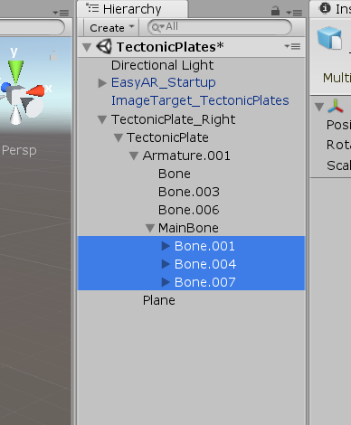
We can now directly modify the “MainBone” object’s rotation instead of these 3 separate objects.
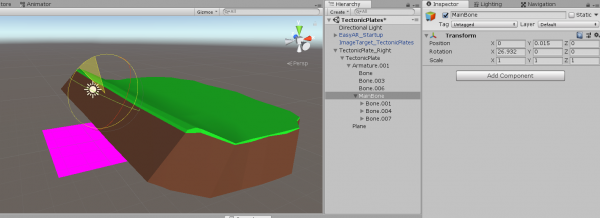
To create the left plate, simply duplicate the “TectonicPlate_Right” object, set the Y rotation of the model to -90 and X position to -5.
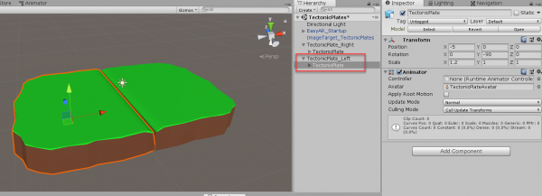
Now, create a new empty GameObject called “TectonicPlates” and center it at 0,0,0. Drag the two tectonic plates into the new empty object as their children.
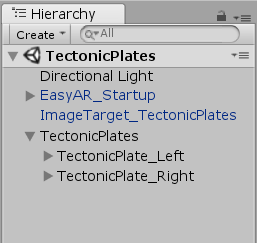
Then, drag the “TectonicPlates” object into the image target as its child. I also set the Y position of it to 0.5, so that it hovers above the image target a bit.

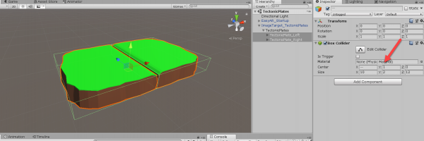
Now we need to attach a BoxCollider2D component to each plate. Resize them so they’re around the size of the model (it doesn’t have to be exact).
Animating the Plates
Now it’s time to start animating the plates. I’m not going to go into much detail of how the animation in Unity works. You can learn about that here.
So first, select the “TectonicPlates” object that holds our 2 plates and go to the Animation window (Window > Animation > Animation). Click the “Create” button and call this first animation “ConvergeOverUnder”. This is going to be the left plate going over the right plate.

The properties we’re going to be animating for each plate is their: position, main bone position and main bone rotation.
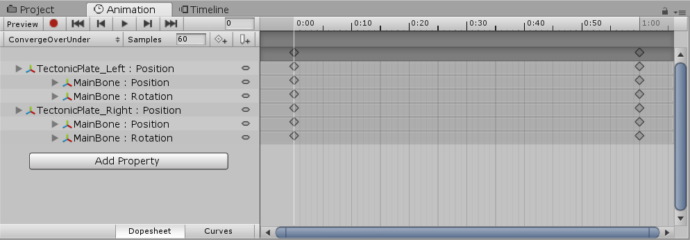
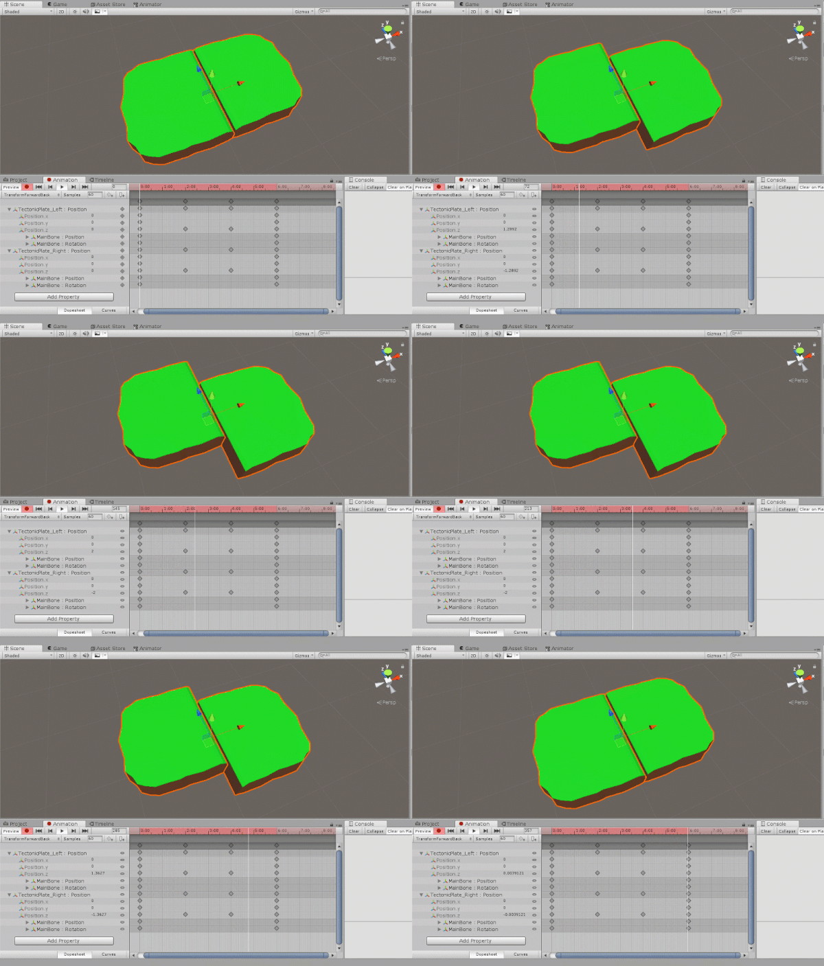
Here’s what the animation should look like. Also make it last 2 seconds. I went into the “Curves” screen and made some of the rotations smoother.
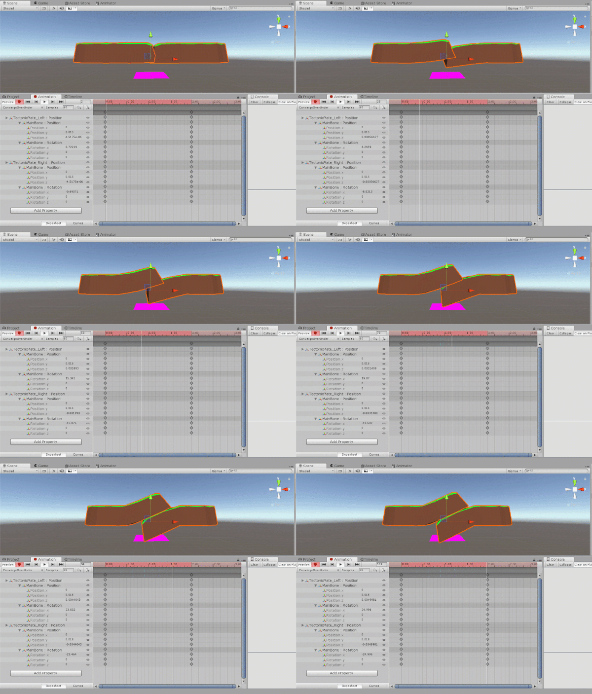
Now we need to make it so that the animation holds for 2 seconds, then returns to the default position. I just copied the key-frames at 2:00 and pasted them at 4:00. Then the same with the key-frames at 0:00 and pasted them at 6:00. This creates a nice looping animation just like the ones seen at the start of the tutorial.
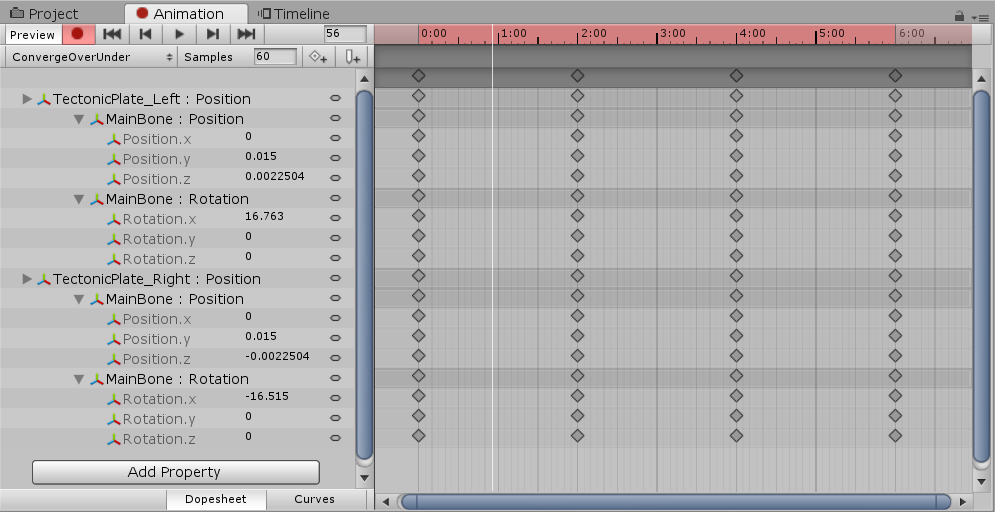
Create another animation called “ConvergeUnderOver”. This is the opposite of the one we just made. What I done, was copy and paste all the key-frames and reverse the position and rotations on each model at each key-frame. This creates the same animation, yet the other way round.
Make sure that the last frame of the friction particle animation, is it going back to 0, 0, 0. This is because an object remains the same as the last frame of animation and we want it to reset to the middle every time.
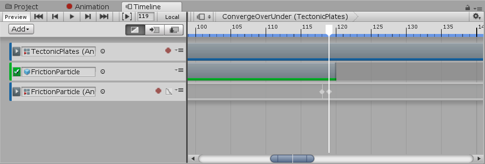
There are a total of 5 animations we need to create.
- ConvergentOverUnder
- ConvergentUnderOver
- Divergent
- TransformForwardsBack
- TransformBackForwards
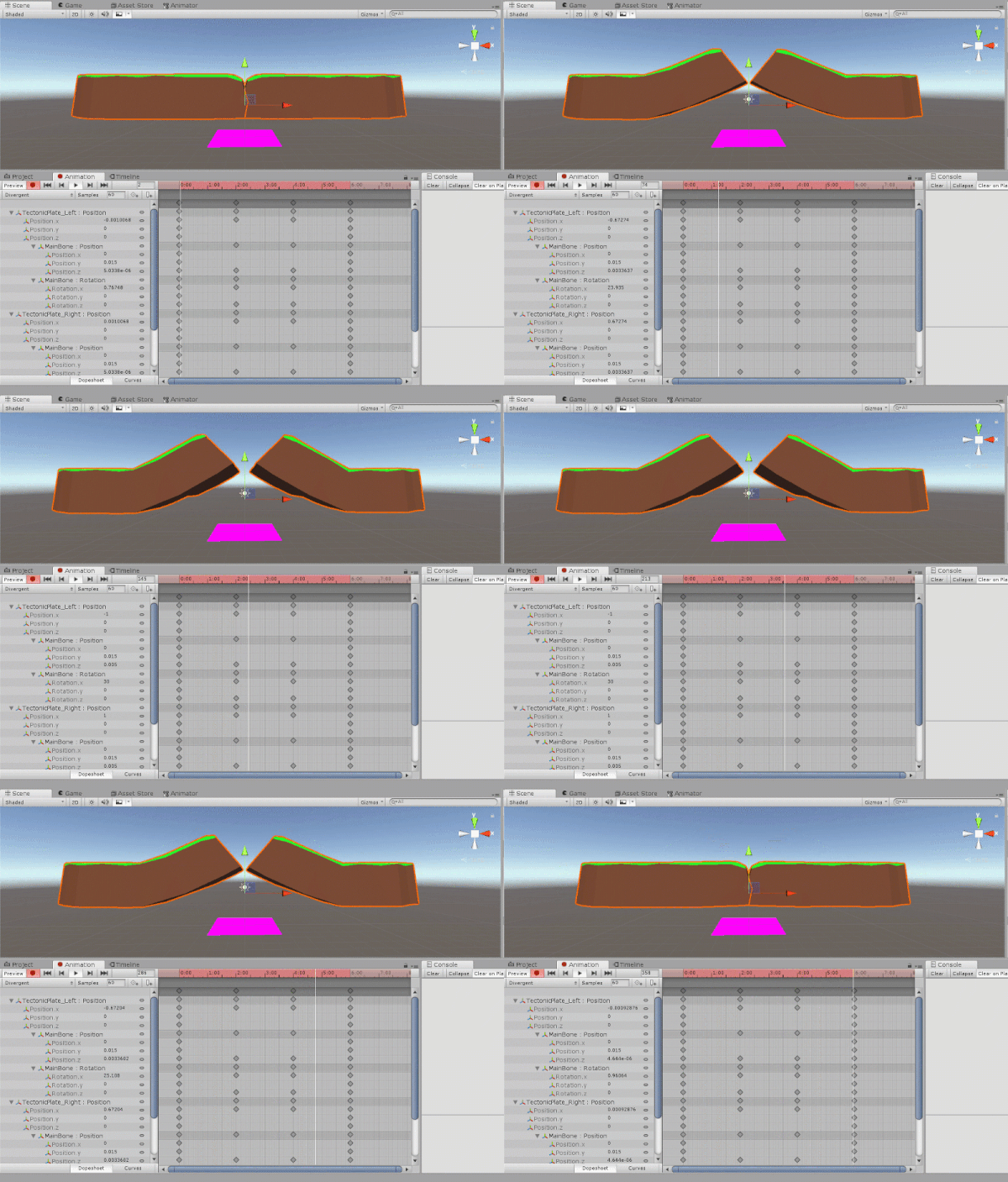
Divergent should look something like this. We’ll be adding in the center part later on.
The TransformForwardsBack and TransformBackForwards animations just need you to animate the Z position of each plate. They are also similar to the convergent animations, where the second animation mirrors the first.
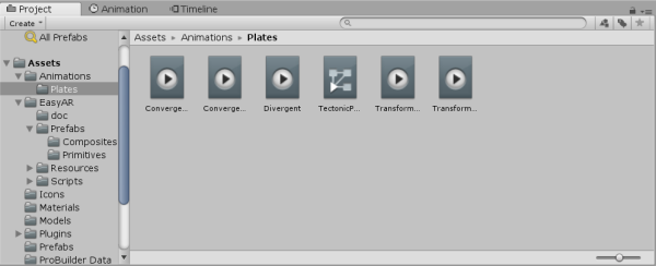
With those done, you should now have your 5 animations and 1 animation controller in the folder.
Creating the Timelines
When we drag and assign a movement for the plates to play, we’re not just going to directly play the animation. What we’re going to do is play a timeline (or playable asset). These are similar to how an animation changes properties overtime. Timelines can play animations at certain times, have objects enabled/disabled, etc. They are essentially used for creating cut-scenes or scripted gameplay sequences. You can learn more about timelines here.
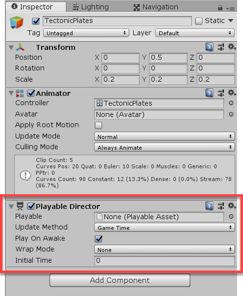
To begin, how animations require an Animator component, timelines require a Playable Director component. Add the Playable Director component to the “TectonicPlates” object. Make sure that you disable “Play on Awake”.
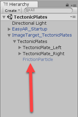
When we animate the plate movement, we’re going to have a friction particle effect playing. Go to the “Prefabs” folder and drag in the “FrictionParticle” as a child of the “TectonicPlates” object. Then deactivate it.
Create a new folder called “Timelines” to hold our timelines. Create a new Timeline (right click Project window > Create > Timeline) and call it “ConvergeOverUnder”. We’re going to be creating a new timeline for each animation, so do that now.
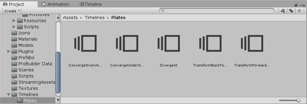
Then we need to open up the Timeline window (Window > Sequencing > Timeline). Click back on the “TectonicPlates” object and drag the “ConvergeOverUnder” timeline into the Playable Director’s “Playable” property. It’s now linked to the object and we can begin editing.
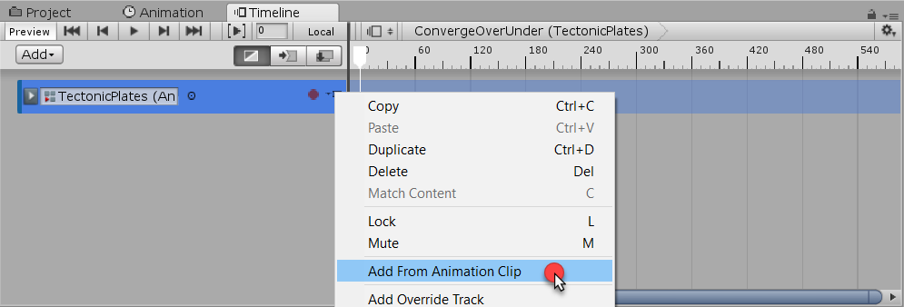
Click the “Add” button and select “Animation Track”. Then drag the “TectonicPlates” object into the property. To select the animation, we need to click on the three black lines near the red circle, and select “Add From Animation Clip”. Select the “ConvergeOverUnder” animation.
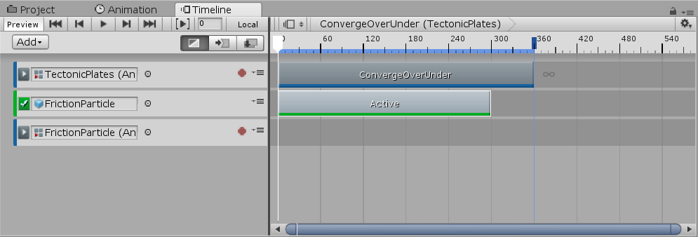
Now drag the “FrictionParticle” object into left hand side of the Timeline window. A popup will appear, select “Add Activation Track”. Then do it again but select “Add Animation Track”.
Now click on the red circle on the friction particle animation track. This will begin to record the object. This is basically an animation. You can now animate the position of the friction particle, so it follows the contact point as the top plate goes over the bottom one.
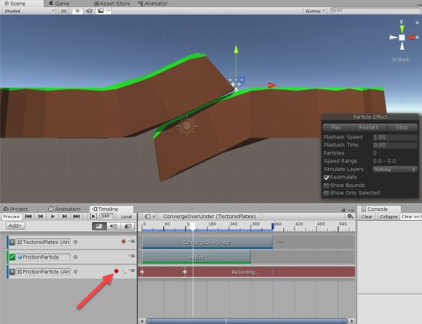
When finished, click on the red circle again to stop recording. Then drag the friction particle active track to make it disable just after the animation stops.
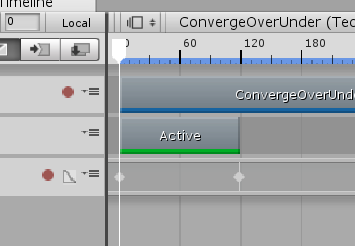
Do the same for the “ConvergentUnderOver” timeline.
Then when we get to the “Divergent” timeline, there’s something we need to do first.
Create a new Cube object (right click Hierarchy > Create > 3D Object > Cube) and make it a child of the “TectonicPlates” object. Also make its material “Earth” so it matches the ground.
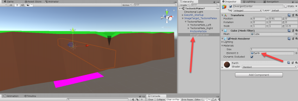
We’re going to animate it in the timeline so that it increases in scale to “blend” the gap between the two plates. After animating, make sure that the object is deactivated so it doesn’t show up in any other timelines.
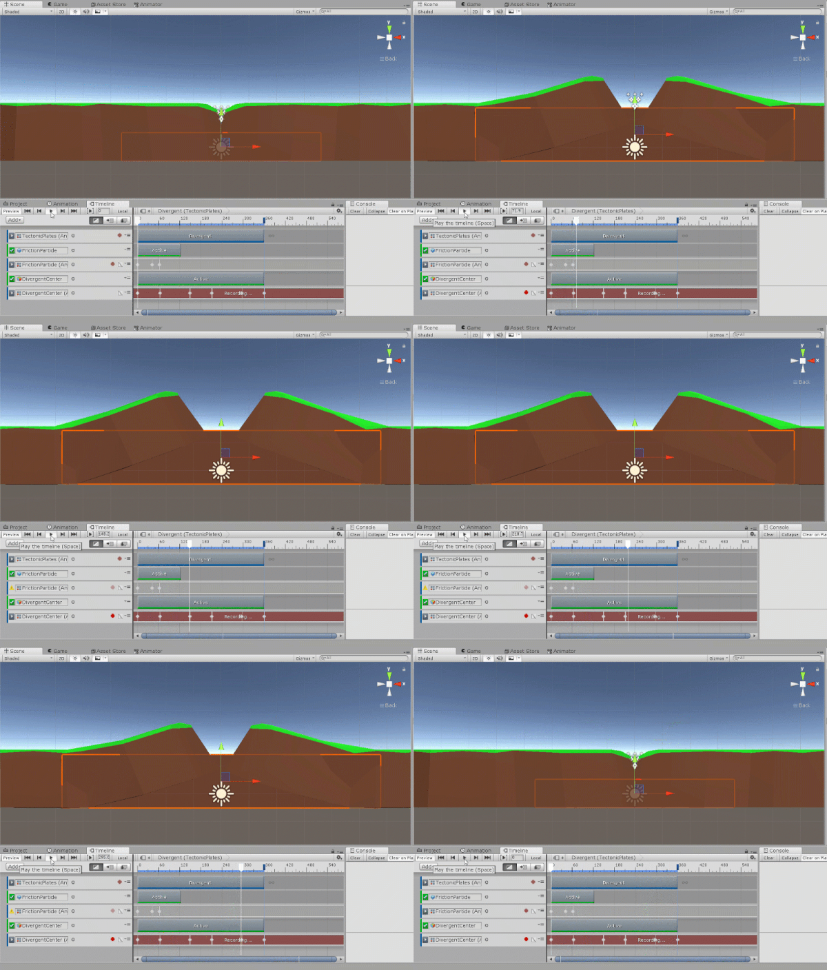
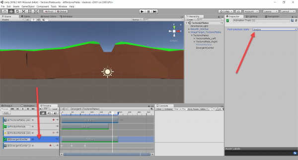
Since the divergent center cube is active until the end of the timeline, that means that it’s going to still be active after the fact. So select the track and change “Post-playback state” to Inactive.
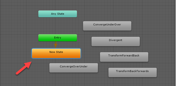
One thing we need to do is set a default animation. So click on the “TectonicPlates” object and double click on the “TectonicPlates” Animation “Controller” property to open it up in the Animator.
By default it’s set to play the first animation we made. So right click in the window and select Create State > Empty. Then right click on that new state and select “Set as Layer Default State”.
Arrow Visual
When we’re dragging a direction on the plates, it would be nice to know which way they were going to move. So we’re going to be adding in an arrow visual. This is simply an arrow sprite that has a nice movement animation.
Drag the “Arrow” prefab from the “Prefabs” folder as the child of each plate’s model. Set their position to 0, 2.2, 0 so that it’s in the center but on the surface of the model.
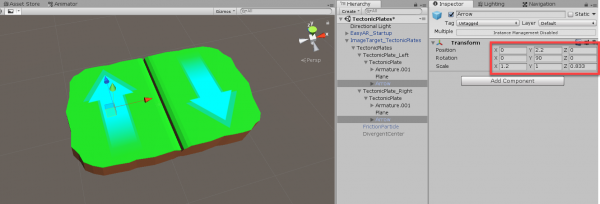
Then deactivate them as we’ll be setting them in code.
Scripting the Plate Info
Now we’re going to begin scripting. First, we need to create a base class for a plate. This will hold various information such as: the game object, assigned movement, arrow object and arrow animator.
Create a new C# script called “Plate” and attach it on the “TectonicPlate_Left” and “TectonicPlate_Right” objects.
This script is just going to contain variables.
public GameObject plateObject;          // plate GameObject
public PlateMovement assignedMovement;  // plate's assigned movement
public GameObject arrowVisual;          // plate's arrow visual object
public Animator arrowAnimator;          // plate's arrow visual Animator component
Now outside of the class, let’s create the “PlateMovement” enumerator.
public enum PlateMovement
{
    Unassigned,         // no assigned plate movement
    TransformForward,   // grinds along other plate positively along Z axis
    TransformBack,      // grinds along other plate negatively along Z axis
    Divergent,          // moves away from other plate
    ConvergentOver,     // converges over other plate
    ConvergentUnder     // converges under other plate
}
By default the plate’s movement is Unassigned.
Starting to Script the Touch Manager
An important script is going to be the touch manager. This is a script which will check for touch inputs, drags and then calculate a direction.
Create a new C# script called “TouchManager” and attach it to a new empty GameObject called “Manager”.
We have 4 variables.
private Vector3 touchStartWorldPos;     // world position where touch began
private Plate touchingPlate;            // plate we are currently touching

// used for double tapping
private float lastTapTime;              // time that the player last tapped the screen
private float doubleTapMaxTime = 0.2f;  // maximum time allowed for a double tap
This is how the touch manager is going to work.

First in the Update function, we check if there are any touches on screen. If so, we check if the touch has began or ended. If it began, check for double tap and set the start touch position. If it ended and we originally dragged from a plate, calculate a drag direction.
void Update ()
{
    // are there any touches on the screen?
    if(Input.touchCount > 0)
    {
        // did the touch START this frame?
        if(Input.touches[0].phase == TouchPhase.Began)
        {
            DoubleTapCheck();
            SetStartTouch(Input.touches[0].position);
        }
        // did the touch END this frame?
        else if(Input.touches[0].phase == TouchPhase.Ended)
        {
            // only calculate if the start touch even touched something
            if (touchingPlate != null)
            {
                CalculateDragDirectionOnPlate(Input.touches[0].position);
            }
        }
    }
}
The “SetStartTouch” function takes in a touch position in pixel coordinates. we then shoot a raycast from the screen towards that touch. If it hits a plate, we set the “touchStartWorldPos” to be the raycast hit point on the collider and set “touchingPlate” to be the hit plate.
// sets the start touch to be a world space position from the screen touch
void SetStartTouch (Vector3 touchPosition)
{
    touchingPlate = null;

    // create a ray from the camera to the touch position
    Ray ray = Camera.main.ScreenPointToRay(touchPosition);
    RaycastHit hit;

    // shoot the raycast
    if(Physics.Raycast(ray, out hit))
    {
        // did we hit anything?
        if(hit.collider != null)
        {
            // set touchStart to be the position the ray hit
            touchStartWorldPos = hit.point;

            // set Y axis to 0 so it's easier to calculate later on
            touchStartWorldPos.y = 0;

            // get the tectonic plate
            touchingPlate = hit.collider.GetComponent<Plate>();
        }
    }
}
In Part 2
In part 2 of the tutorial, we’ll be continuing with the touch manager, setting up the plate manager to run the timelines, and a UI text.
